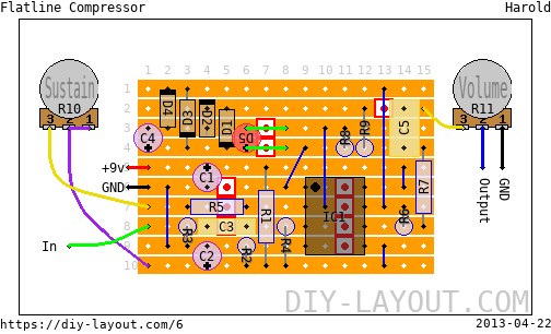
Flatline Compressor
Posted Mon, 2009-09-07 23:48 by Harold

Project description
A nice and transparent compressor based on this schematic by John Hollis.
The weird LED/green wire combination represents an optocoupler. I've used the VTL5C2 in 2 of my builds. Here's a nice read about them optocoulers and LED/LDR combo's: http://home.orange.nl/fvrijswijk/guitar_electronics_diy/flatline_compres...
The flatline is really suitable for use on bass and can even give a nice boost to drive a tube amp into fat crunch!
Bill of materials
| Resistors | |
|---|---|
| R1: 10K | |
| R2: 10K | |
| R3: 10M | |
| R4: 10M | |
| R5: 10K | |
| R6: 47K | |
| R7: 10K | |
| R8: 220K | |
| R9: 330R | |
| Potentiometers | |
|---|---|
| R10: 100K Log (A) | |
| R11: 100K Log (A) | |
| Capacitors | |
|---|---|
| C3: 1nF | |
| C5: 1μF | |
| Electrolytes | |
|---|---|
| C1: 10μF | |
| C2: 10μF | |
| C4: 100μF | |
| DIL IC's | |
|---|---|
| IC1: TL072 | |
| Diodes | |
|---|---|
| D1: 1N34A | |
| D2: 1N34A | |
| D3: 1N34A | |
| D4: 1N34A | |
| LEDs | |
|---|---|
| D5: 5mm | |
| 6 jumper wires |
| 10 trace cuts |
List
Click here to see the bill-of-materials as a list or download it as a comma separated values file (.csv).
Code
BB Forum code
HTML code

Comments
RE: R10 lug 3....
Submitted on April 22nd, 2013 by AnonymousSorry, lug 1.
D
Lug 1
Submitted on April 22nd, 2013 by adminD, Lug 1 is attached to lug 2 ... I agree, brown on brown is a bit hard to see, let me fix that ;)
On a side note: it doesn't change the workings of the potentiometer, which is wired as variable resistor in this case.
RE: Lug 1 (2)
Submitted on April 25th, 2013 by AnonymousMany Thanx for that !
So i'm connecting a wire from lug 1 to lug 2. Is that right ?
I am really sorry if i'm coming across like I need to be walked through this but I am really new to this and don't want to get it wrong.
Thanx again
Dean
Lug 1 and 2
Submitted on April 25th, 2013 by AnonymousSorry for wasting time....spotted it. D'oh !
Dean
R10 - lug 3...
Submitted on April 22nd, 2013 by AnonymousSorry again for the ridiculous questions :-) but is lug 3 on R10 not used. What I mean is, is it not used for the ground ?
Thanx
D
The weird LED/green wire combination
Submitted on April 16th, 2013 by AnonymousFirstly, i'm extremely new to circuit building and stomp boxes so please bear with me if this sounds obvious....
Do I need to put in the LED and the wires ? If so, is it just a normal LED conected across the two tracks with the green wires passing over the cuts ?
Thanx in advance :-)
D E Holt
P.S. Great great site by-the-way :-)
D5
Submitted on August 14th, 2012 by AnonymousHeey,
Is D5 de Led/ldr combinatie of de VTL5C2? En dan aan de kant waar de led staat de led en aan de andere kand de weerstand?
Mvg,
Chapzz
Je mag zelf kiezen maar ik
Submitted on August 15th, 2012 by adminJe mag zelf kiezen maar ik vind de VTL5C2 wel het beste werken in deze compressor. Het LED-gedeelte zit waar de LED op het bordje is getekend en de LDR dus aan de rechterkant.
Quick translation: the LED-part of the optocoupler is where the LED is drawn on the board, the LDR part is at the right side lf the LED.
RE: D5...
Submitted on April 16th, 2013 by AnonymousMany thanx for that. I think i've got it.
Great stuff