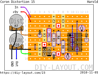
Coron Distortion 15
Posted Sun, 2009-12-13 23:35 by Harold

Project description
Bill of materials
| Resistors | |
|---|---|
| R2: 51K | |
| R3: 68K | |
| R4: 510K | |
| R5: 10K | |
| R6: 3.3K | |
| R8: 1.5M | |
| R9: 10K | |
| Potentiometers | |
|---|---|
| R7: 500K Log (A) | |
| R10: 50K Log (A) | |
| Capacitors | |
|---|---|
| C2: 10nF | |
| C3: 2.2nF | |
| C4: 47nF | |
| C6: 10nF | |
| Electrolytes | |
|---|---|
| C1: 10μF | |
| C5: 10μF | |
| DIL IC's | |
|---|---|
| IC1: LM741P | |
| Diodes | |
|---|---|
| D1: Germanium | |
| D2: Germanium | |
| 4 jumper wires |
| 9 trace cuts |
List
Click here to see the bill-of-materials as a list or download it as a comma separated values file (.csv).
Code
BB Forum code
HTML code

Comments
VERIFIED....
Submitted on April 13th, 2012 by AnonymousWhen you build the properly it works.....faithful repro of original Coron 15 which I am lucky enough to own. Nice project, not too complex. I used OA90 diodes, but LEDs or other diodes should work. Also, just use the closest possible values, if you can't get the actual exact ones !
Good luck, it took me a few attempts to get it going, the eyes are not what they used to be.
Circuit verified....no excuses!
Moderators please Ignore my last post about the 741orientation
Submitted on April 12th, 2012 by AnonymousI will rebuild and confirm whether it works.
Profuse apologies to Harold
This coron 15 strip board layout cannot possibly work
Submitted on April 12th, 2012 by AnonymousOkay I traced the circuit and feasibly this looks good. But here's the problem, the 741 chip is not mounted directly onto the pcb copper side, it is physically mounted, as should all of the components be, from the non copper strip board side and soldered onto the copper side where the legs poke through. The 741 chip correctly has the number 1 pin marked with a black circle for orientation purposes, however, this changes when the chip is mounted from the rear ie non copper side, and the legs soldered onto the copper side. whilst orientation is not a problem for all of the 2 legged components, it is for multi egged components. Nicely laid out, just does not work! I am an electronics engineer with 27 years experience, I was building this with my son, when we noticed the problem. I will try and troubleshoot this, one obvious solution perhaps is to reverse the legs on the chip so it is effectively turned upside down.
Please remove I posted this in error
Submitted on April 12th, 2012 by AnonymousI have since rebuilt this and it works just fine.
Build
Submitted on August 16th, 2011 by AnonymousCan anyone verify this build.
VERIFIED !!!!
Submitted on April 12th, 2012 by AnonymousBuilt it today and it works just fine....I will AB it with a Coron 15 I have sat around, although it looks authentic enough in terms of values of components etc...can't see why it would sound any worse at all. Niceley laid out and very compact. If you are from UK just use the nearest value components. I had to opt for OA90 germanium diodes (this is all Maplin had at the time). Although LEDS / other diodes should work fine as well.
Nice one Harold!!
Thanx!
Submitted on April 17th, 2012 by adminThank you for verifying it!
I really should spend more time on DIYL ... :(