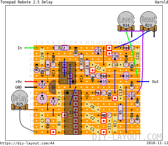
Tonepad Rebote 2.5 Delay
Posted Sun, 2010-10-24 01:34 by Harold

Project description
Let's call this one "advanced". ;)
This is a verified layout of Tonepad's Rebote 2.5 delay. I built it using Greenies, but I strongly advise against them now! They are just too big for such a project... Use MKT's to get all the caps on such a small board. This will fit nicely in a B enclosure but just don't use greenies! You may want to use 100nF for the 82nF's.
Lower R18 to 10k or 11k to allow for self-oscillation. A 6.8k in series with a trimpot of 5k might be easier to find the correct value.
Bill of materials
| Resistors | |
|---|---|
| R1: 1K | |
| R2: 12K | |
| R3: 12K | |
| R4: 12K | |
| R5: 24K | |
| R6: 2.7K | |
| R7: 24K | |
| R8: 24K | |
| R9: 100K | |
| R10: 33K | |
| R11: 47K | |
| R12: 12K | |
| R13: 12K | |
| R14: 12K | |
| R15: 1K | |
| R16: 240K | |
| R17: 510K | |
| R18: 15K | |
| R19: 12K | |
| R20: 12K | |
| R21: 510K | |
| R22: 1M | |
| Potentiometers | |
|---|---|
| R23: 25K Linear (B) | |
| R24: 100K Linear (B) | |
| R25: 50K Linear (B) | |
| Capacitors | |
|---|---|
| C1: 82nF | |
| C2: 82nF | |
| C4: 100nF | |
| C5: 560pF | |
| C6: 1nF | |
| C7: 100nF | |
| C8: 100nF | |
| C10: 10nF | |
| C11: 10nF | |
| C12: 10nF | |
| C14: 51pF | |
| C17: 10nF | |
| C18: 27nF | |
| C20: 5pF | |
| C21: 100nF | |
| C24: 82nF | |
| Electrolytes | |
|---|---|
| C3: 47μF | |
| C9: 100μF | |
| C13: 1μF | |
| C15: 1μF | |
| C16: 1μF | |
| C19: 1μF | |
| C22: 47μF | |
| C23: 47μF | |
| DIL IC's | |
|---|---|
| IC1: PT2399 | |
| IC2: TL072 | |
| Transistors | |
|---|---|
| Q1: 78L05 | |
| 8 jumper wires |
| 30 trace cuts |
List
Click here to see the bill-of-materials as a list or download it as a comma separated values file (.csv).
Code
BB Forum code
HTML code

Comments
Just Built this and all that
Submitted on February 12th, 2013 by AnonymousJust Built this and all that comes through is noise, adjusting the pots changes the pitch, volume. Any ideas what might have gone wrong? Or any advice on how I might trouble shoot it? Thanks
Nick
As always,
Submitted on February 12th, 2013 by adminAs always,
* Check the offboard wiring
* Scrape all track "gutters" clean with the tip of a knife. If your knife can get through easily, remove solder and redo that part.
* Measure(!) resistance between tracks for "invisible" jumpers
* Check component values
This is a verified build, so if you made your's properly it shoud function just fine!
There's also a hell of a lot
Submitted on February 12th, 2013 by AnonymousThere's also a hell of a lot of heat coming from where the 9v joins the board, Plus my LED doesn't work so do you think it could be a problem with the 9v/board joint?
Nick
working fine, a little
Submitted on January 6th, 2013 by Anonymousworking fine, a little distortion when you put the "delay" button between 80 and 100%
thank for your work !
perhaps you could wire a 220
Submitted on November 3rd, 2011 by Anonymousperhaps you could wire a 220 and a 20 in series
Two questions: -C20: Would a
Submitted on December 9th, 2010 by AnonymousTwo questions:
-C20: Would a 4.7 pF capacitor work, or does it have to be exactly 5 pF?
-R16: Would a 220K resistor work, or does it have to be exactly 240K?
Thanks in advance!