Xotic RC Booster
Posted Tue, 2010-08-10 12:00 by Harold

Project description
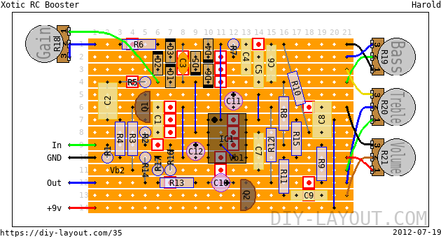
This is a layout of the famous Xotic RC Booster, based on one of the many schematics out there. I've built one myself and was quite impressed with it but I switched back to my old LPB-1 for sake of simplicity.
Bill of materials
| Resistors | |
|---|---|
| R1: 1M | |
| R2: 10K | |
| R3: 1M | |
| R4: 10K | |
| R5: 22K | |
| R6: 47K | |
| R7: 4.7K | |
| R8: 33K | |
| R9: 10K | |
| R10: 4.7K | |
| R11: 470K | |
| R12: 10K | |
| R13: 470R | |
| R14: 100K | |
| R15: 22K | |
| R16: 6.8K | |
| R17: 15K | |
| Potentiometers | |
|---|---|
| R18: 250K Linear (B) | |
| R19: 50K Linear (B) | |
| R20: 50K Linear (B) | |
| R21: 100K Linear (B) | |
| Capacitors | |
|---|---|
| C1: 47nF | |
| C2: 1μF | |
| C3: 150pF | |
| C4: 4.7nF | |
| C5: 33nF | |
| C6: 33nF | |
| C7: 4.7nF | |
| C8: 1μF | |
| C9: 100nF | |
| Electrolytes | |
|---|---|
| C10: 10μF | |
| C11: 10μF | |
| C12: 10μF | |
| DIL IC's | |
|---|---|
| IC1: JRC4558D | |
| Diodes | |
|---|---|
| D1: 1N4148 | |
| D2: 1N4148 | |
| D3: 1N4148 | |
| D4: 1N4148 | |
| D5: 1N4148 | |
| D6: 1N4148 | |
| Transistors | |
|---|---|
| Q1: 2N3904 | |
| Q2: 2N3904 | |
| 6 jumper wires |
| 22 trace cuts |
List
Click here to see the bill-of-materials as a list or download it as a comma separated values file (.csv).
Code
BB Forum code
HTML code

Comments
Foot Switch type?
Submitted on October 23rd, 2012 by AnonymousHi can you please confirm what type of foot switch is required a 3dpt or a dpdt?
Thank you.
Standard wiring
Submitted on October 23rd, 2012 by AnonymousI always use a 3PDT like this: http://diy-layout.com/56
Thanks for your reply
Submitted on October 24th, 2012 by AnonymousHi thanks for your reply, although if not using an LED why the need for a 3DPT, wouldn't a DDPT be sufficient?
Thanks.
Yep
Submitted on October 24th, 2012 by AnonymousThe third row/switch of a 3PDT is used for switching the ground of a LED. A 2PDT or DPDT is enough for a true bypass without LED.
DPDT Switch?
Submitted on October 22nd, 2012 by AnonymousThanks for the brilliant website!!
Only 1 question... does this pedal need a DPDT Switch or is it a different type?
Thanks again.
Trace cuts
Submitted on October 16th, 2012 by AnonymousHi I'm totally new and am starting to build my self one RC Booster as above because I need it. In the BOM page it says that there are 22 "trace cuts". Could anyone clarify where these cuts should be made? Thank you for your help. Dom.
Tracecuts are the red and
Submitted on October 17th, 2012 by adminTracecuts are the red and white squares on the stripboard. Cut the copper traces there by twisting a 3 or 4mm drill with your fingers.
It is probably working but it
Submitted on September 23rd, 2012 by AnonymousIt is probably working but it is not the original schematic. I have opened mine and there are 3 transistors not 2, 6+1+2=9 diodes not 6, the IC is a JRC4557 and the 2 same transistors are 2SC1815
Analog Yann
If you can find an updated
Submitted on October 17th, 2012 by adminIf you can find an updated schematic, I'll fix the layout for it!
I've build it myself, but
Submitted on January 27th, 2011 by HaroldI've build it myself, but that report may be biased since I also made the layout ;)
News? :)
Submitted on September 20th, 2011 by AnonymousHi! I want to build this pedal, is it working? How it should be biased?
Looking other schems, I've just seen 3 diodes, while you're using 6 of them... why? :)
Btw, does it works as the original unit (so it's a Really Clean boost)?
Thanks!
Biassing is not needed since
Submitted on September 20th, 2011 by adminBiassing is not needed since there are no transistors on it ;) It has 6 diodes to keep the distortion down to a minimum. I believe the AC booster only has 3 diodes which increases clipping. The AC Booster is nearly identical to the RC booster.
Verified?
Submitted on January 23rd, 2011 by AnonymousHi! Great pedal and great schematic... but is it 100% working? Thanks! :)