IC Buffer
Posted Thu, 2009-12-03 12:35 by Harold

Project description
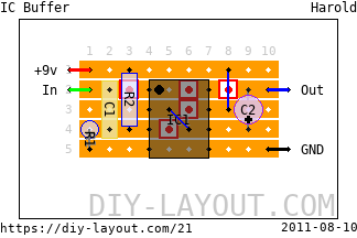
Based on this schematic by Jack Orman and the layout by Carsten Bocker.
Verification status
There seems to be an error in the layout, although I remember building one that worked?!? Anyway: give me a few days to sort it out and I'll get back on this!
Mods
Use 2.2M for R1 and R2 for higher input impedance (General Guitar Gadgets).
Bill of materials
| Resistors | |
|---|---|
| R1: 1M | |
| R2: 1M | |
| Capacitors | |
|---|---|
| C1: 100nF | |
| Electrolytes | |
|---|---|
| C2: 10μF | |
| DIL IC's | |
|---|---|
| IC1: TL071 | |
| 2 jumper wires |
| 5 trace cuts |
List
Click here to see the bill-of-materials as a list or download it as a comma separated values file (.csv).
Code
BB Forum code
HTML code

Comments
IC Buffer layout
Submitted on August 10th, 2011 by AnonymousHi there,
There are 2 errors on the above layout :
- a cut trace is missing under the IC, between PIN 4 & PIN5 respectively VCC - & OFFSET N2
- the ground must be wired between R1 & IC PIN4 on the other side of row #5
Will this fix it? A cut trace
Submitted on June 1st, 2012 by AnonymousWill this fix it?
A cut trace is missing under the IC, between PIN 4 & PIN5 respectively VCC - & OFFSET N2
To fix: Cut position (5 along, 5 down)
The ground must be wired between R1 & IC PIN4 on the other side of row #5
To fix: Connect (3 along, 5 down) to (8 along, 5 down) with a wire.
Thanx!
Submitted on August 10th, 2011 by adminThank you for reporting, I've edited the description and I'll have a look at it as soon as I have some time...
Cheers!
Hi there is this circuit
Submitted on April 26th, 2013 by AnonymousHi there is this circuit correct? I built it as is but it didn't work, although I can't see how the suggested changes would make any difference as the cut would break the ground connection between pin 4 and 5 and the suggested wire jumper would just add it straight back?
Anyone built a working one of these?
I haven't tried to build this
Submitted on May 8th, 2013 by AnonymousI haven't tried to build this buffer yet but it seems like pin 5 does not need to go to the ground. So the jumper from R1 & pin 4 is not needed. All you have to do is put the ground wire in between R1 & pin 4 and make sure that pin 4 & 5 are not connected by drilling out one of the traces. Let me know what you think.